0769-82730118
CH
National consultation hotline
0769-82730118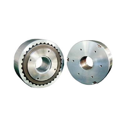
|
Model |
Rated torque |
Rated current |
Voltage |
Coil resistance (At 25℃±10%) |
Weight |
Rated slip power |
Peak speed |
|
|
5 minutes |
continued |
|||||||
|
kg·cm |
mA |
VDC |
Ω |
kg |
watts |
watts |
rpm |
|
|
LB-202 |
2 |
200 |
24 |
120 |
0.41 |
75 |
20 |
5000 |
|
LB-302 |
3 |
390 |
24 |
62 |
0.9 |
120 |
35 |
5000 |
|
LB-502 |
5 |
390 |
24 |
62 |
0.9 |
120 |
35 |
5000 |
|
LB-103 |
10 |
400 |
24 |
60 |
1.70 |
320 |
80 |
3000 |
|
LB-203 |
20 |
315 |
24 |
76 |
3.40 |
460 |
115 |
3000 |
|
LB-303 |
30 |
1200 |
24 |
20 |
5.12 |
680 |
165 |
2500 |
|
LB-503 |
50 |
1200 |
24 |
20 |
9.30 |
1000 |
200 |
2000 |
|
LB-114 |
100 |
1200 |
24 |
20 |
22.0 |
1200 |
350 |
1800 |
|
LB-124 |
120 |
1200 |
24 |
20 |
22.0 |
1200 |
350 |
1800 |
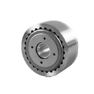
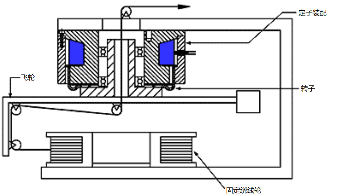
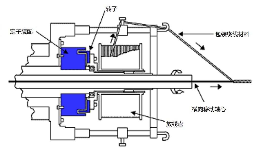
Typical application-hollow shaft hysteresis brake
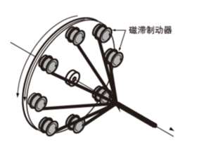
The hollow shaft brake is installed in an optical fiber stranding machine to control the tension of the packaging material.

Flywheel control: The brake electrode/housing is composed of bolts fixed on the frame, and the hollow shaft with bearings is installed in the electrode. The hollow shaft, rotor and flywheel form an assembly to tighten the winding material.

Wechat Scanning

Scanning & Download