
0769-82730118
CH
National consultation hotline
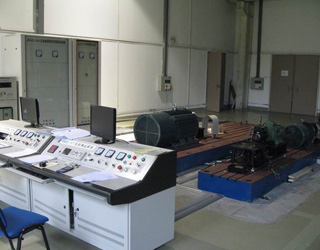
0769-82730118The structure of the dynamometer is very simple. It consists of a cabinet and a test bench. The test bench is often called the dynamometer head. It generally refers to a model in which a torque speed sensor and a brake are integrated. The test bench includes mounting base, torque and speed sensor, mechanical load (brake); the cabinet includes electrical parameter tester, motor tester, dynamometer controller, power supply, etc. The functions of each component are as follows:
l Installation base-used to install and fix the tested motor;
l Torque and speed sensor-used to collect the speed and torque of the motor under test;
l Mechanical load-generally use brakes, and some motors are used to provide reverse rotation torque to the motor under test, absorb the power of the motor under test, realize the "load" of the motor under test, and simulate its actual operation. Working condition;
l Electrical parameter tester-used for the collection and display of electrical parameters such as voltage, current and electrical power of the tested motor;
l Motor tester-used to collect the output signal of the torque and speed sensor and digitally display the speed, torque and mechanical power of the motor under test;
l Dynamometer controller-used to control the mechanical load to output different torque;
l Power supply-used for power supply of the system and the motor under test.
For users, the dynamometer solves the most troublesome problem-loading and data collection, but the processing of test results still needs to be done manually.


Wechat Scanning

Scanning & Download