0769-82730118
CH

Hysteresis Brake

Current Position:Home > Product > Hysteresis Brake > Hysteresis Brake

Hysteresis Brake

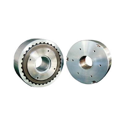
Product name:LB series hollow shaft hysteresis brake

Based on the standard hysteresis brake, the bearing and core shaft device are removed, and a fixed hole is added to the rotor to provide constant tension control for the passive unwinding of the wire.
  • Product Details
Working principle
  The hysteresis effect in magnetism is applied to torque control by using two basic components, a mesh pole structure and a special steel rotor/shaft assembly are installed together, but not in physical contact. Before the pole structure is energized, the towing cup can rotate freely on its bearings. When the magnetizing force from the excitation coil is applied to the pole structure, the air gap becomes a magnetic flux field and the rotor is magnetically confined, thereby providing braking or clutching between the pole structure and the rotor.
  The superior design of these hysteresis devices provides several inherent advantages over magnetic particles and friction devices. They operate under frictionless design principles with little wear. This has the following advantages: longer life expectancy, better torque repeatability, life cycle cost advantage, wide speed range, excellent environmental stability and excellent operational fluency.


  In current-controlled hysteresis brakes, torque adjustment and control is provided by the excitation coil. This allows full control of the torque by adjusting the DC current of the excitation coil. Adjustable from a minimum value (bearing resistance) to a maximum value of 10-20% above the rated torque. These brakes use the same working principle as our permanent magnet hysteresis brakes, but the magnetic field is replaced with a magnetic field coil, which provides the precise magnetic field strength required for the rated torque.


  Residues than the magnetic force:

  residual magnetism when the field current is suddenly changed less than 50% of the initial value and is not generated when the rotor is rotated, the torque fluctuation will occur during operation. Effective methods to avoid torque fluctuations are:
  • Manually turn the stator and rotor separately while gradually reducing the excitation current
  • Gradually reduce the excitation current
  before the equipment is shut down • Disconnect the low excitation current before the equipment is shut down (between the stator and the rotor) Relative speed is above 100 rpm)


  Specification parameter table of LB series hollow shaft hysteresis brake:
 

Model

Rated torque

Rated current

Voltage

Coil resistance

(At 25℃±10%)

Weight

Rated slip power

Peak speed

5 minutes

continued

kg·cm

mA

VDC

Ω

kg

watts

watts

rpm

LB-202

2

200

24

120

0.41

75

20

5000

LB-302

3

390

24

62

0.9

120

35

5000

LB-502

5

390

24

62

0.9

120

35

5000

LB-103

10

400

24

60

1.70

320

80

3000

LB-203

20

315

24

76

3.40

460

115

3000

LB-303

30

1200

24

20

5.12

680

165

2500

LB-503

50

1200

24

20

9.30

1000

200

2000

LB-114

100

1200

24

20

22.0

1200

350

1800

LB-124

120

1200

24

20

22.0

1200

350

1800


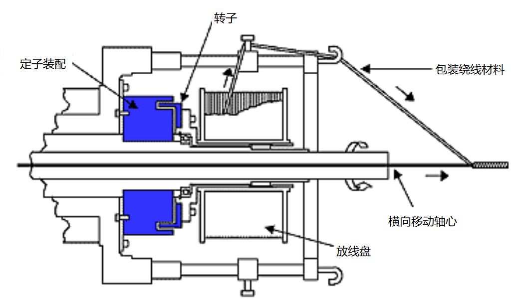
  Typical application-hollow shaft hysteresis brake
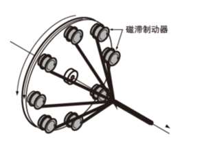
 

  The hollow shaft brake is installed in an optical fiber stranding machine to control the tension of the packaging material.


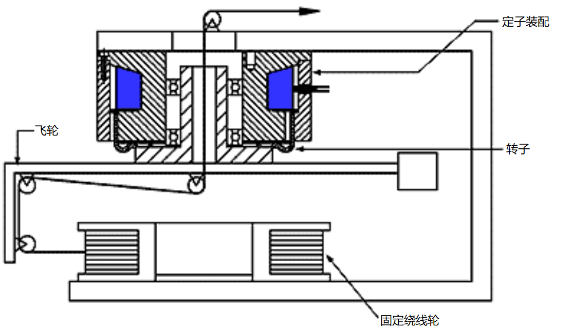
  Flywheel control: The brake electrode/housing is composed of bolts fixed on the frame, and the hollow shaft with bearings is installed in the electrode. The hollow shaft, rotor and flywheel form an assembly to tighten the winding material.


Recommendation of relevant cases

We'd like to hear your opinion

Whether you want to know us or have any suggestions, we will be glad to hear from you.